Learn about Parts
In electronics, we deal with two main units: voltage (V), which is the difference of potential between two points (think of the force pushing electrons to go from one point to another), while current (I) is the amount of electrons passing through a given point.
In the beginner world, there is always a common ground, called VSS, GND or 0V. It’s a point where there is no potential, so all the electrons want to go there. Thus if you connect a point that has 5V to GND, electrons will naturally flow from 5V to GND.
Now onto the components! All these come in the kit.
Resistors
One of the fundamental parts of electrical design is resistors, which are used to limit the current flow. They are used in places where we want to stop components from using up too much electricity, and getting hot then burning itself. Each resistor has a certain resistance value, measured by ohms (Ω).
They are characterized by it’s resistance, given by the formula R = V / I, which is also known as Ohm’s law.
If you put two resistors in series, their resistance combine: It is equivalent to one resistor that has the resistance of the sum of the two original resistors. When two or more resistors are parallel, their total resistance is given by the formula 1/Rtotal = 1/R1 + 1/R2 + 1/R3 + …

Photoresistor
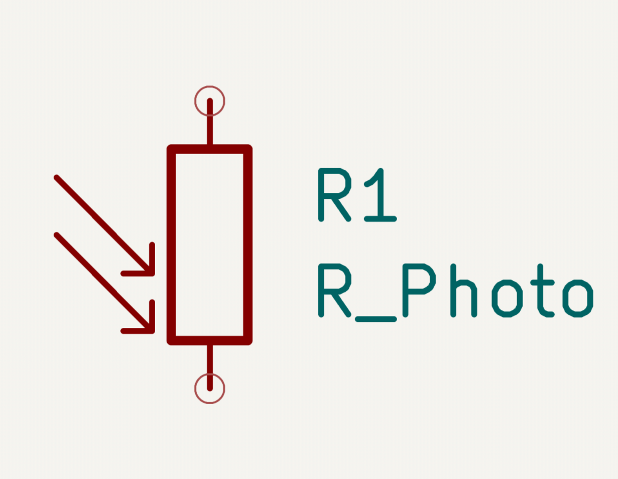
Photoresistors are basically the same as resistors, but their resistance decreases when they are subject to light, and increases when they are in the dark.

Capacitors
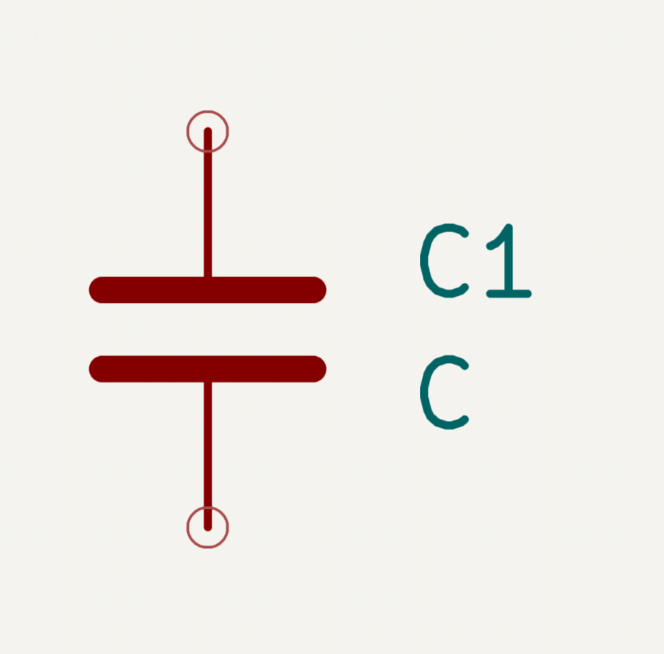
Capacitors are like tiny batteries, they charge up when you apply a voltage across them, and their internal voltage increase. And discharge when the outside voltage is lower then their internal voltage.

Buttons
Buttons do what they do! Press em and they will conduct a current. They have 4 pins, but each pair is actually connected together so it’s actually 2 pins.

Vibration motors
Vibrates when current is passed through! Use potentiometers or resistors to limit their speed.

Potentiometer
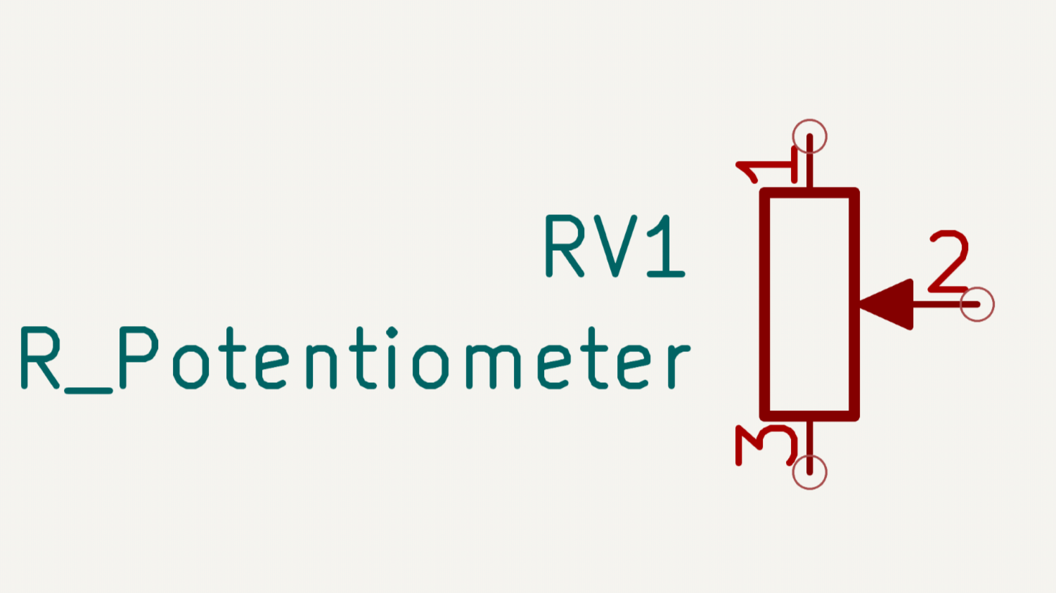
Potentiometers have 3 terminals, and act as a variable resistor. By connecting the two ends, they act as a constant resistor, but the pin in the middle is special, it has variable resistance from one end of the potentiometers to the middle pin. If you want adjustable resistance, just wire up one end of the potentiometer, and use the middle pin as output.

Transistors
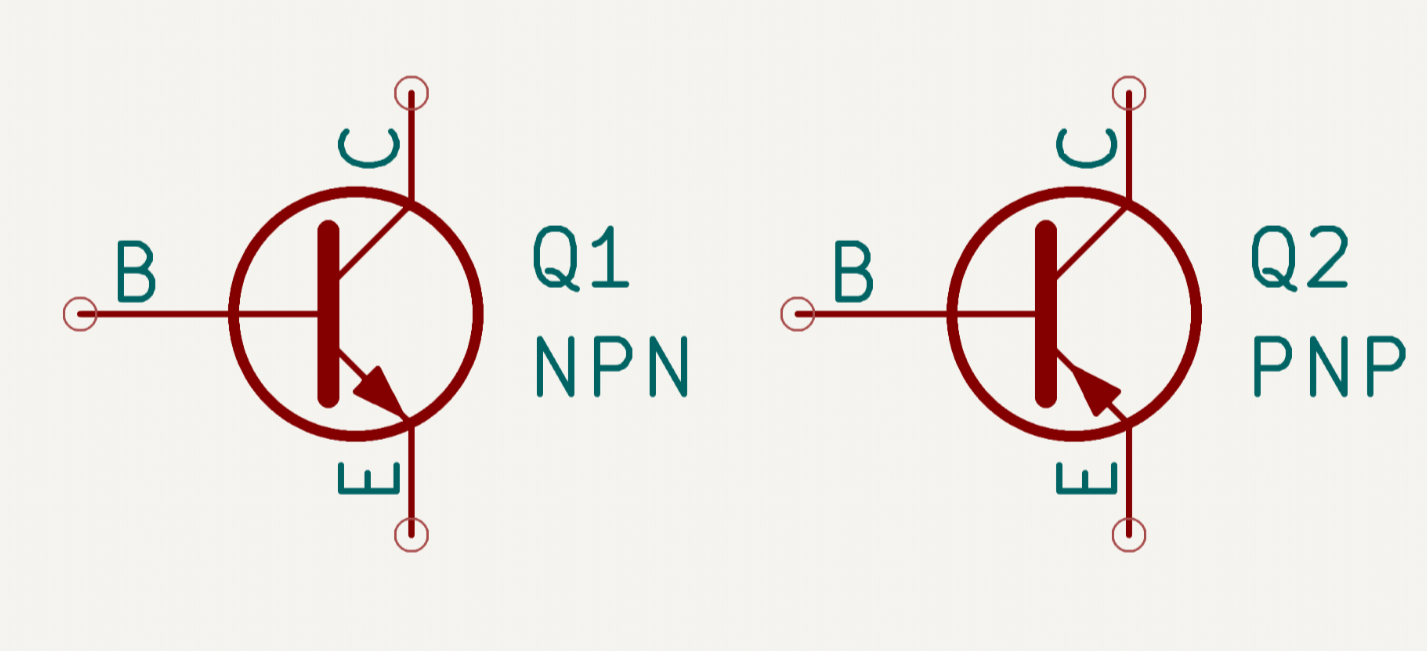
A transistor is a device that allows you to use change in voltage to switch things on and off. They are kind of like a valve, but instead of controlling water they control electricity. They are divided into NPN and PNP types, and they have three pins, called emmiter, collector and base (also called gate).

In the case of a NPN transistor, the emmiter is where the electrons exits, the collector where the electrons enters. The gate is basically the switch. If the voltage on the gate is higher then on the emitter, the transister will allow electricity to pass. Inversly, if the the voltage gate is lower or equal to the emitter, the transistor will not allow electrons to pass.
But the switches are not perfect, electricity will also conduct from the gate to the emitter, so if you don’t put a resistor on the gate, you might cause a short circuit. The current allowed to pass through the gate is also important. Each amp of current that can pass through the gate will generally allow ~100 amps of electricity to pass from the collector to the emitter. Calculate the current on the gate with ohms law! Also don’t make your circuit depend too much on this, the 100 will change to 60 or 140 depending on temperature!
The PNP transistor is the inverse of a NPN transistor: The base needs to be at a lower voltage than the emitter for electricity to flow. When the base is at the same voltage as the emitter, it doesn’t allow any electricity to pass through.

Diodes
Diodes are simple electrical components that only allows electricity to flow in one direction. When you see a diode on the schematic, it is often represented with a small triangle with a bar, which represents that electricity can only flow in the direction the triangle is pointing to.

LEDs
LEDs are the same as diodes (They are called Light Emitting Diodes after all), but they emit light when electricity flows through it! Remeber to add a 220 ohm resistor on one end, so the LED doesn’t burn itself.
